
With the demand for greener data centers that can support higher bandwidth at long distances steadily growing, fiber patch cables are being used for installations more frequently. In order to establish which fiber optic cable is most appropriate for the job, two primary layers must be understood first: the core and cladding.

The Core
At the core of an optic cable is a cylinder made of either glass or plastic. Cladding, which is what surrounds the core, is also made of glass or plastic.
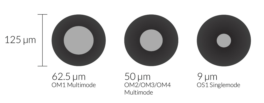
The amount of light that is able to transmit through the fiber is dependent on the diameter of the outer core: The larger the core, the more light is able to pass through. Finding the diameter of the outer core is done by finding the average of the diameters of the smallest circles restricted to the core-cladding boundary. The mode field diameter is another measurement that defines the maximum intensity of light. Singlemode fiber has a larger diameter due to light entering the cladding.
There are three common core sizes: 62.5/125 (62.5 µm), 50/125 (50 µm) and 9/125 (9 µm) and they are measured in microns, which equates to one-millionth of a meter. Singlemode fiber has a narrow diameter at 8.3 to 10 microns and the diameter ratio of the core to cladding is 9 to 125 microns. Multimode fiber can come with a wide diameter of 50 to 100 microns, but the most common size is 50/125. The diameter ratio of the core to cladding for multimode fiber is 50 to 125 microns.
The Cladding
Cladding is made of reflective material that surrounds the core. This not only helps keep light within the core, but also helps move it through the length of the fiber. Light can sometimes saturate the core as well as the cladding, so it is important that the cladding supports various refractive indexes as well as modes. Modern fibers are built with a higher refractive index than that of the cladding to ensure the quick dissipation of light.
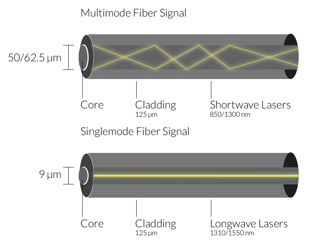
More data is able to be transmitted through a multimode fiber optic cable because the light wave disperses into numerous paths within the core. However, the signal loses strength over long distances. Singlemode fiber optic cable, on the other hand, has a narrow sized core which decreases the amount of light reflections and increases the strength of the signal to travel over longer distances. However, less data is able to be transmitted compared to multimode fiber optic cable.
The Coatings
The multiple layers of plastic that surround the fiber are called coatings. These coatings act as a buffer to preserve strength, absorb shock, and add an additional layer of protection. They come in a variety of microns, from 250 to 900.
Core-cladding Concentricity
There are a number of factors that can affect the loss of connection between two optical fibers. The most notable is core-cladding concentricity; this affects the quality of light transmission. Other factors include fiber core to fiber cladding as well as ferrule edge to ferrule bore. Having the diameter of the fiber mirror the diameter of the bore can also affect the concentricity.
ICC’s fiber patch cables are individually inspected to not exceed 1.5 microns, which helps keep the core as close as possible to the center. This inspection helps remove the possibility of misalignment and decreases optical loss within the core-cladding offset.

Bandwidth versus Distance
The chart below shows the comparison between fiber optic bandwidth and distance. As the data rate in bandwidth increases, the distance decreases.
| Data Rate | Fast Ethernet 100BA SE-FX |
1Gb Ethernet 1000BASE SE-SX |
1Gb Ethernet 1000BA SE-LX |
10Gb Base SE-SR | 40Gb Base SR4 | 100Gb Base SR10 | ||
|---|---|---|---|---|---|---|---|---|
| Category | Type | Core | Distance | |||||
| OS1 | Singlemode | 9/125 | 200 meters | 5K meters | 5K meters | 10K meters | Not Supported | Not Supported |
| OM1 | Multimode | 62.5/125 | 200 meters | 275 meters | Not Supported | 33 meters | Not Supported | Not Supported |
| OM2 | Multimode | 50/125 | 200 meters | 550 meters | Not Supported | 82 meters | Not Supported | Not Supported |
| OM3* Laser Optimized |
Multimode | 50/125 | 200 meters | 550 meters | Not Supported | 300 meters | 100 meters | 100 meters |
| OM4* Laser Optimized |
Multimode | 50/125 | 200 meters | 550 meters | Not Supported | 400 meters | 150 meters | 150 meters |
This chart displays the differences between Singlemode and Multimode fiber optic cables. Singlemode OS1, covers up to 10,000 meters, which is 50 times more than what multimode can cover. Multimode comes in four different categories: OM1, OM2, OM3, and OM4. The most commonly used are the OM1 and OM2. These fibers are used to support 1Gb Ethernet applications and are supported themselves with 10 Gigabit Ethernet (10GbE) at a length of 33 meters and 82 meters, respectively. OM3 and OM4 cables, which are laser-optimized, are also supported by 10GbE but can run distances of 300m and 550m.
Visit ICC’s Fiber Optic System solution page to learn more.